Introduction / Home
Process (short)
More Process Details
Notes on JOSM Files
PicLayer Files
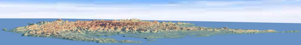
Territory Examples
AN149
PE007
Ridges & Settings
Spread & Cliffs
Granularity & Roughness
Ridge Rounding
Other Objects
LakesFlats
Custom Objects
Miscellaneous
Current Issues
Possible Projects
Fractal Noise
More Details on the Process
JOSM is used to set and store settings in one or more OSM files that are read by a custom program written in Java. You can download one of the main render files (AN149, or PE007) to get an idea of how of how the settings are stored.
Base Layer: Base elevations are set and rendered into their own layer. Noise is added and the layer is slightly blurred to remove hard edges and rounding-error artifacts. A low continental shelf is added to avoid a drop-off at the edges or at coastlines, that would result in high coastline and/or edge erosion areas later in the process.
Ridges and custom objects will have their elevations either added to the base layer elevations (additive method), OR the higher of the two elevations is used (higher method). The 'additive' method complicates accurately setting elevations. For example: A base layer point set at 100m with 200m object placed on top will result in a 300m height. The 'higher' method would produce a final value of 200m.
The additive method seems to give better results, and allows wide areas to be adjusted up and down by only changing the base layer.
Base layer settings can be set in the same layer as the other settings, or in their own OSM file/layer to avoid clutter in the main OSM file. The base layer is optional and can be ignored if needed.
Custom Objects and Mounds: Previously created objects can be added to the height-map. For example: custom topographic features, temporary placement markers or existing height-maps.
Ridges: For each ridge object, a straight-line featureless ridge is created based on height width, length and settings of the ridge way. Multiple passes of noise are applied to add detail and obscure artifacts caused by the noise algorithm. A Bezier curve based on the original way node positions is used to distort the ridge in to its final shape.
Lakes: Lakes are added to the height-map, getting their elevations from the lowest elevation along the lake's final shoreline. A shallow drainage basin leading to the low point is created. The shoreline is blended into the surrounding areas. Currently, all elevations inside the lake are set to the elevation of the lake, flattening all topography inside the bounds of the lake.
Flats: Generated by the same basic process as lakes, flats force a specified area to a set elevation, and then adjust the surrounding area to make the flat look less unnatural. Helpful for setting a location for an airport or town. Flats can also be used to shape shorelines by forcing an area's elevation under sea-level.
Drainage Channels (Ditches): After the initial render, drainage channels are added to the height-map. Low areas that are completely surrounded by higher areas will be filled during the low-point fill at the next step. To avoid large flat filled areas, drainage channels provide exit paths for water and eroded sediment. Drainage channel locations are based on water paths from a filled version of the height-map. Odd results (channels cut directly across a ridge) can occur since the filled hight-map may have covered topographic features that were set at lower elevations.
Low Point Fill: Every point on the height map is checked, starting at the point with the lowest elevation(s) and ending at the highest, to make sure a natural drainage path for water exists. Elevations that do not have a drainage path available are filled until "water" has a way to flow out.
A second fill is added after the height-map has been eroded. Filling, eroding, and then filling again gives better results than first eroding and filling once.
Erosion: Simulated hydraulic erosion is used to add detail. The amount of erosion can be adjusted, but currently the same strength/value is used for all points. This means that areas meant to be rock will erode as at the same rate as areas that are meant to be sand. (A strength layer could be added for more control.)
Topo Map: The final height map data is used to create a topographic map and a PicLayer calibration file to display the results in JOSM. Water path traces are added and show the paths water would take to reach lower elevations. Some of the water paths can look odd because the underlying topography is odd. Straight-line water paths are an indication that more detail might be needed.
Currently there is no assigned/calculated real-world value for water volume. The color of the paths is based on a percentage of the highest amount of water up to a point, after which the path color goes to dark blue.
Note: In most cases, when objects are added to the height-map, higher elevation points overwrite lower elevation points. The current exceptions are lakes and flats which change elevations based on settings.